
Built redundancy beats paper.
Your A and B feeds look separated on paper. In the ceiling void they share a tray. You find out at commissioning.
Verify every redundancy path in 3D before concrete is poured
Three things to prove in the model before concrete is poured.
Power & cooling, proven in 3D
Electrical and cooling paths modelled and clash-checked before concrete.
Redundancy you can verify
Every N+1 / 2N path traced in the model: redundancy on paper becomes redundancy in the build.
White space & modular deployment
Rack layouts, containment and modular blocks coordinated for fast, repeatable roll-out.
From shell-and-core to commissioning
Three stages. Click any to expand the deliverables and BIM requirements at that stage.
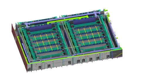
Federated MEP models at LOD 400 with power and cooling redundancy verified before tender release. A and B paths confirmed physically separated. White space layout proven against rack density and tier targets.
Key processes
Power & cooling routing
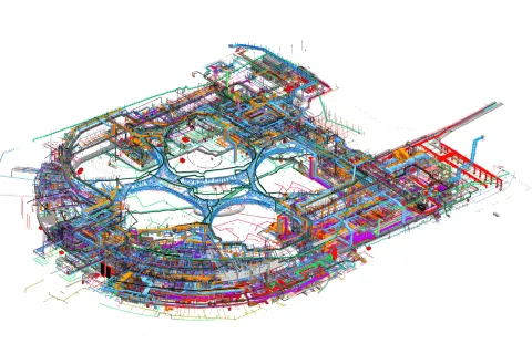
Primary and redundant paths coordinated across HV, LV, UPS, generators, and cooling plant in a single federated model.
White space layout
Rack positions, containment, and services verified per hall for density and connectivity before fit-out scope is fixed.
Redundancy path verification
A and B feeds confirmed physically separated throughout the building, risers, ceiling voids, and cable trays audited in 3D.
Deliverables
- Federated MEP models (LOD 400)
- Power and cooling redundancy models
- White space layout and rack planning models
- Raised floor and busbar coordination
- Coordinated GA and tender drawings
BIM requirements
BEP with redundancy protocols
Execution plan includes redundancy verification rules, power-path modelling standards, and commissioning gates from day one.
CDE by hall & tier
File structure mirrors data-hall layout and tier classification so every discipline works against the right redundancy requirements.
LOD by commissioning gate
Level of detail tied to design freeze, factory acceptance, and commissioning milestones, not generic project stages.
Hall-by-hall fit-out packages with redundancy verification reports and MEP sequencing models. Modular release with confirmed tie-in points to shared plant. Clashes resolved in the model, not in the ceiling void.
Key processes
Modular phase release
Hall-by-hall fit-out packages issued with confirmed tie-in points to shared power and cooling plant.
MEP installation sequencing
Power, cooling, and cable management installation coordinated per zone so trade overlap is planned not improvised.
Commissioning preparation
Equipment schedules and manufacturer data embedded for commissioning readiness from procurement onward.
Deliverables
- Hall-by-hall fit-out packages
- Redundancy path verification reports
- MEP installation sequence models
- Tie-in point coordination per phase
- Commissioning preparation packages
BIM requirements
Clash cycle
Weekly federation reviews per hall with issues tracked in BIM Track to closure before installation.
LOD 400 audit
Risers, plantrooms, and busbar runs validated against fabrication tolerances and manufacturer geometry.
Synchro linking
Model objects mapped to hall-by-hall programme activities with tie-in dependencies surfaced.
As-built models, COBie data, and equipment schedules ready for handover without an additional data-gathering phase. Redundancy paths confirmed post-construction. FM and commissioning teams inherit a model that reflects the as-installed building.
Key processes
Commissioning data
Every piece of critical infrastructure carries full asset data, manufacturer specs, maintenance schedules, spare-parts info, embedded from procurement.
As-built verification
As-built models per hall confirm all systems installed per design. Redundancy paths re-verified against the as-installed building.
Commissioning-ready handover
Complete asset data and FM documentation delivered at practical completion. No separate data-gathering phase.
Deliverables
- As-built models per hall
- COBie asset data per system
- Equipment and manufacturer schedules
- Commissioning-ready handover documentation
- Maintenance and spare-parts registers
BIM requirements
COBie validation
Asset data audited against the EIR's information requirement schedule, system-by-system.
IFC final drop
IFC 4.0 federation deposited in CDE with EIR sign-off attached per hall and per tier.
FM system handshake
Asset data mapped to client CAFM / EAM schema before transfer so commissioning teams plug straight in.
Six services. One delivery system
Every service we apply to a data centre runs through the same standard. Redundancy verified in 3D. White space planned hall by hall. Commissioning data embedded from procurement. FM-ready at handover.
BIM Delivery
Power, cooling, white space and structural shell coordinated as one federated model at LOD 400 before tender.
Explore service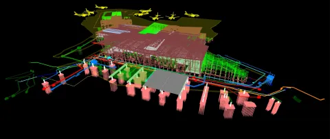
Virtual Design & Construction
4D hall-by-hall deployment phased against demand. 5D power, cooling and fit-out costs tracked per phase. Redundancy paths confirmed in the model.
Explore service
Information Management
CDE structured by hall and tier. ISO 19650 enforced across MEP specialists. EIR and BEP carry redundancy protocols.
Explore service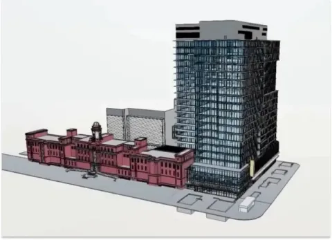
Digital Twins
Asset data structured by hall and system for commissioning-ready handover. No separate data-gathering phase.
Explore service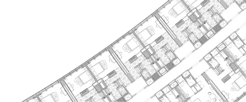
QTO & Cost
Quantities extracted per hall, per system, per phase. Power, cooling and busbar takeoffs your QS can trust at tender.
Explore service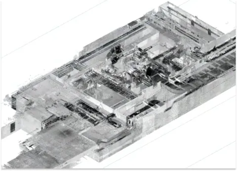
As-Built Documentation
LiDAR scan-to-BIM per hall. Redundancy paths re-verified against installed conditions before commissioning sign-off.
Explore serviceWalk through Stargate Data Centre with us.
A 30-minute screen-share through the live federated model from our data-centre portfolio. We open the coordinated model, the clash log, the shop drawings and the handover dataset, and you ask what you would on your own project.
- Project
- Stargate Data Centre
- Format
- 30-min screen-share · live federated model · Q&A
- Audience
- Developers · Consultants · Main Contractors
Data centres we've coordinated
From hyperscale shell-and-core to edge fit-out. Six selected projects covering power, cooling, white space and as-built verification.
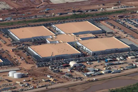
Stargate Data Centre
Every N+1 and 2N redundancy path verified in 3D against Tier-rating requirements…
Read the case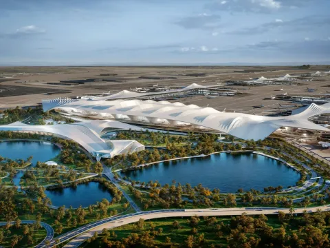
DWC Airport
Terminal-scale design packages for Dar Al-Handasah on Dubai World Central's next…
Read the case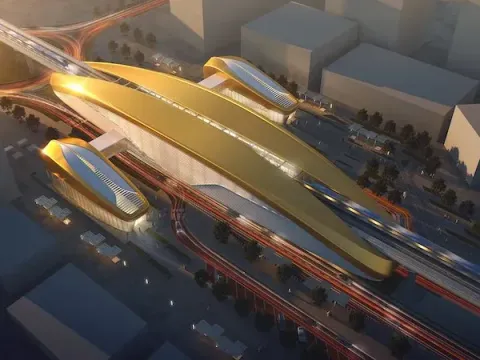
Dubai Metro Blue Line
MEP modelled and coordinated across Blue Line stations and depots for MNG Esmas,…
Read the case
Wynn Ras Al Khaima
Over 100 people at peak across MEP, structural and interior fit-out packages on …
Read the case
Zayed National Museum
Mechanical, electrical and plumbing threaded through Foster + Partners' steel-fe…
Read the case
Emaar Golf Hillside Tower
Shop drawing release synced to the tower pour cycle on AFE's fast-track golf-fac…
Read the case
Al Badia
Every consultant and contractor on Al-Futtaim's master-planned villa and low-ris…
Read the case