
50 engineers. Same standard.
MEP BIM services across all five systems, coordinated, clash-resolved, fabrication-ready. One team, one standard, project one to ten.


Scale five systems. Same quality on every one
Production capacity without hiring
HVAC, electrical, plumbing, fire, and drainage engineers scaled from one studio. No recruitment lag. Capacity flexes with your project pipeline.
Same standard, every engineer
ACA quality gates on every system. ERP-tracked progress across HVAC, electrical, plumbing, and fire. Same coordination standard on project 1 as project 10.
Single point of accountability
One team across all five systems. No chasing separate providers for HVAC, electrical, and plumbing coordination. One responsibility matrix. One federated model.
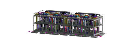
MEP in production
Six views from live MEP packages, federated models, plant rooms, riser sections, spool extracts, 4D phasing, clash visualisations.
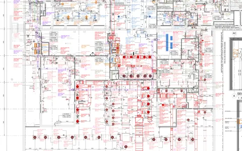
Get the MEP drawing pack.
Real MEP drawings from completed projects: HVAC and services layouts, coordinated multi-service views, fabrication-ready spools and hanger details. The drawings we actually issue, not a brochure, so you can judge the standard before you brief anyone.
- Contents
- 4 documents · PDF + Revit / Navisworks samples
- Drawn from
- Completed MEP packages, redacted
- Audience
- MEP Managers · BIM Coordinators · Main Contractors
Routing through commissioning. One discipline
Three phases. Click any to expand the key processes, deliverables, and BIM requirements at that stage.
Schematic pipe and duct runs to fully coordinated MEP layouts. We develop services models that integrate with architecture and structure from the earliest design stage, so routing decisions are locked in before detailed design.
Key processes
Model setup from BEP
MEP worksets, system classifications, shared coordinates aligned with architectural and structural grids, so every discipline works from the same baseline.
System-by-system modelling
HVAC, plumbing, electrical, fire protection developed as separate linked models with cross-discipline referencing, so conflicts are caught before installation.
Spatial allocation review
Ceiling voids, risers, plant rooms, and service corridors assessed for routing feasibility before detailed design, so space is reserved and protected.
Deliverables
- Schematic MEP models (LOD 200)
- Developed services models (LOD 300)
- HVAC ductwork and plant layouts
- Pipework routing and riser diagrams
- Electrical containment layouts
- Lighting and power distribution models
BIM requirements
Classification & Clearances
Elements classified per Uniclass 2015. 150mm soft clash zones verified by automated rule checks for access.
Naming Convention
Pipe, duct, and cable tray families named per project standard with size, system abbreviation, and level reference embedded in type parameters.
Information Exchange
IFC 2x3/4.0 exports with MEP-specific property sets validated before each data drop to the CDE.
Construction-ready MEP models with installation-level detail, manufacturer-specific equipment, and fully resolved coordination against all adjacent disciplines for zero-clash site delivery.
Key processes
LOD 400 model development
Manufacturer-specific equipment, valve assemblies, access panels, and support brackets modelled for installation coordination, so fabricators have shop-drawing-ready data.
Weekly clash detection cycles
MEP versus architecture, structure, and inter-service clashes tracked with hard (0mm) and soft (25-100mm) tolerance thresholds resolved before site delivery.
Plant room coordination
3D sectional views with maintenance access clearances, pull-through zones for cables, and valve stem reach verified against manufacturer data.
Deliverables
- Construction-issue MEP model (LOD 400)
- Fabrication-ready spool drawings
- Coordinated plant room layouts
- Clash detection reports (Navisworks)
- Equipment and valve schedules
- Hanger and support coordination
BIM requirements
Clash & Equipment Data
Hard clashes 0mm, soft clashes 25-100mm per service type. Equipment data embedded and signed off.
Coordination Log
All inter-discipline issues tracked in centralised log with owner, priority, target date, and linked model view reference per BEP protocol.
Prefabrication Export
Spool drawings exported as shop-drawing-ready packages with ISO dims, weld locations, hanger positions, and material call-offs.
Verified LOD 500 model with asset tags, COBie data sheets, and FM-ready exports. Your facilities team inherits a model that's accurate, complete, and ready to plug into their systems.
Key processes
As-built verification
MEP model updated from contractor red-line markups, commissioning data, and point cloud survey for all installed services routes and equipment positions.
COBie data population
Serial numbers, commissioning dates, warranty expiry, maintenance intervals, spare parts lists, and supplier contacts embedded per maintainable asset, so FM has structured data, not a spreadsheet to re-enter.
System zoning for FM
MEP model tagged with maintenance zones, isolation valve locations, distribution board references, and access point identifiers for FM operational use.
Deliverables
- Verified as-built MEP model (LOD 500)
- COBie data sheets (UK 2012 compliant)
- FM platform-ready IFC export
- Equipment asset register
- Maintenance schedule matrix
- O&M documentation package
BIM requirements
Asset Data & COBie
Every asset tagged with unique ID and linked to BMS. 100% COBie fields: serial numbers, manufacturer, maintenance intervals.
Spatial Accuracy
As-built model within 25mm tolerance, verified against laser scan or survey for primary distribution routes.
Handover Format
Revit + IFC 4.0 + COBie + PDF O&M manual per employer information requirements, validated against project AIR.
Eliminate routing conflicts and cost surprises
Visualise installation sequences floor by floor. Validate routing against budget before procurement. Changes that would overrun cost are flagged in real time so you can iterate early.
4D Scheduling
Sequence MEP installation floor by floor and zone by zone. Access conflicts are visible before site mobilisation so your team can plan safely.
5D Cost Modelling
Link component quantities to cost plans. See the budget impact of routing changes in real time. Costs stay aligned with programme, not surprises at procurement.
Prefab Optimisation
Identify prefabrication opportunities from the coordinated model. Reduce on-site labour and accelerate installation. Spool sheets generated automatically.
MEP work we've coordinated
Mechanical, electrical, plumbing, coordinated in production. Shop drawings, clash resolution, BMS and fire integration across hospitality, infrastructure, and data-centre projects.

Qiddiya Water Theme Park
Pools, ride mechanical and themed landscape services federated in one model acro…
Read the case
DWC Airport
Terminal-scale design packages for Dar Al-Handasah on Dubai World Central's next…
Read the case
Dubai Metro Blue Line
MEP modelled and coordinated across Blue Line stations and depots for MNG Esmas,…
Read the case
Wynn Ras Al Khaima
Over 100 people at peak across MEP, structural and interior fit-out packages on …
Read the case
Stargate Data Centre
Every N+1 and 2N redundancy path verified in 3D against Tier-rating requirements…
Read the case
Zayed National Museum
Mechanical, electrical and plumbing threaded through Foster + Partners' steel-fe…
Read the case
Emaar Golf Hillside Tower
Shop drawing release synced to the tower pour cycle on AFE's fast-track golf-fac…
Read the caseFrom the journal
Field notes on MEP delivery.
 6 min
6 min
From LOD 350 to fabrication-ready
Why "coordinated" models still cause site rework, and the handoff that fixes it.
Read 5 min
5 min
The BEP subcontractors actually follow
The difference between a filed document and a working agreement is five sections.
Read 5 min
5 min
Clash detection to zero
Zero hard-clash is table stakes. Here is the tolerance standard we hold a federated model to before sign-off.
Read 6 min
6 min
QTO as the single source of truth for variations
When quantities come straight from the model, variations stop being arguments and become deltas.
Read 5 min
5 min
As-built from day one
Retrofitting an as-built at practical completion is a tax. Updating it weekly is a habit.
Read