
Signage clashes late.
Signage zones, mounting details, clearance envelopes , coordinated against structure, MEP and interiors before fabrication. One team, one standard, every zone.


Coordination in 3D before anything gets fabricated
Production capacity without hiring
Wayfinding strategists, signage modellers, and mounting coordinators from one studio. No hiring. Capacity matched to your signage programme.
Same standard, every engineer
ACA quality gates on every sign placement, mounting detail, and electrical coordination. ERP-tracked. Same standard across every zone.
Single point of accountability
One team across signage, structure, MEP, and interiors coordination. No late-stage clashes at installation. One responsibility matrix.
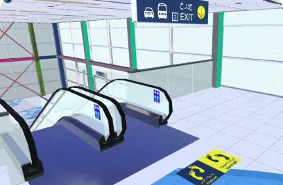
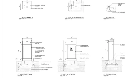
Signage in production
Six views from live signage and wayfinding packages, strategy plans, sign family libraries, mounting details, fabrication-ready models, sightline studies, and as-built schedules.
Get the signage drawing pack.
Real signage drawings from completed projects: sign location plans, sign type matrices, fabrication drawings and mounting details. The drawings we actually issue, not a brochure, so you can judge the standard before you brief anyone.
- Contents
- 4 documents · PDF + Revit / Navisworks samples
- Drawn from
- Completed signage packages, redacted
- Audience
- Wayfinding Designers · BIM Coordinators · Main Contractors
Strategy through installation. One team
Three phases. Click any to expand the key processes, deliverables, and BIM requirements at that stage.
From wayfinding strategy and sign family definition to fully positioned signage models coordinated with architecture, interiors, and MEP. We develop signage BIM that captures sign types, mounting details, sightline verification, and regulatory compliance, so design decisions are locked before fabrication.
Key processes
Wayfinding strategy modelling
Visitor routes, decision points, and sign placement logic developed from circulation analysis with sign positions verified against architectural floor plans.
Sign family development
BIM families created for each sign type (directional, identification, regulatory, informational, digital) with parametric dimensions, material finishes, and mounting types.
Sightline verification
Visibility cones modelled at each sign position to verify legibility distance, viewing angle, and obstruction clearance against columns, bulkheads, and furniture.
Deliverables
- Wayfinding strategy and visitor flow maps
- Sign type family library (BIM families)
- Sign position and location plans
- Sightline and visibility cone analysis
- Illuminated sign coordination model
- Signage GA plans and typical details
BIM requirements
Sign Library & Position
Types modelled as parametric families with dimensions, material, and finish. Positions to +/-25mm from gridlines per DDA.
Sightline Standards
Legibility distance, character height, and contrast ratio verified per BS EN 12899 and BS 8300.
MEP Coordination
Illuminated signs coordinated with electrical routes and circuit references. Power demand schedule extracted per floor.
Fabrication-ready signage models with mounting details, electrical coordination, and installation sequencing. Enabling specialist signage contractors to manufacture and install with precision against the coordinated building model.
Key processes
LOD 400 model development
Every sign modelled with fabrication-level detail including bracket types, fixing bolt patterns, cable entry points, and surface finish specifications per manufacturer.
Mounting detail coordination
Wall substrates, ceiling framing, and floor fixings verified at each sign position with structural capacity checks and backing plate requirements documented.
Setting-out extraction
Sign positions dimensioned from survey control with mounting heights, offset dimensions, and rotation angles extracted per floor for installation contractor.
Deliverables
- Fabrication-ready signage model (LOD 400)
- Sign mounting and fixing detail packages
- Electrical connection coordination
- Setting-out plans per floor and zone
- Sign schedule with message content
- Structural loading verification log
BIM requirements
Fabrication & Structural
Material spec and text content embedded. Structural capacity and suspension loads verified with SE sign-off.
Electrical Schedule
Electrical schedule extracted per sign. Circuit reference, wattage, control zone, and emergency lighting documented.
Installation Tolerance
Setout +/-5mm internal, +/-10mm external. Alignment verified against architectural features and grid lines.
As-built signage model verified against installed positions. Populated with message schedules, maintenance data, and replacement specs. Ready for FM and future tenant or branding changes.
Key processes
As-built verification
Signage model updated from installation records and as-built photographs to reflect actual sign positions, mounting types, and message content as installed on site.
Message schedule population
Current text content, language versions, pictogram references, and branding guidelines embedded per sign with revision tracking for future tenant changes.
Illumination data entry
Lamp type, colour temperature, expected lamp life, driver specification, and replacement procedure documented per illuminated sign for FM maintenance planning.
Deliverables
- Verified as-built signage model (LOD 500)
- Sign asset register and message schedule
- Illumination maintenance data sheets
- Replacement sign specification log
- Digital display O&M documentation
- Model handover audit report
BIM requirements
Asset Data & Messages
Signs tagged with unique ID, type, illumination, and installation date. Message content and branding linked for updates.
Maintenance Data
Lamp replacement intervals, cleaning frequency, and inspection schedule documented per sign type and circuit.
Handover Format
Revit + IFC 4.0 + COBie + sign schedule PDF + O&M manual per employer asset info requirements.
Validate wayfinding before fabrication starts
Sequence installation zone by zone and coordinate with MEP electrical. Test wayfinding effectiveness before fabrication. Component quantities generated automatically so fabrication is on time.
4D Installation Sequencing
Sequence zone-by-zone installation coordinated with MEP electrical. Installation plans are validated before your team arrives on site.
5D Fabrication Quantities
Link component quantities to specifications and costs. Fabrication lead times are tracked against programme so delays are caught early.
Wayfinding Simulation
Validate pedestrian flow. Test sign placement, sightlines, and comprehension before fabrication so changes cost nothing.
Signage work we've coordinated
Wayfinding strategy, brand integration, and signage coordinated through the model from schematic design through installation, alongside MEP and interiors.

DWC Airport
Terminal-scale design packages for Dar Al-Handasah on Dubai World Central's next…
Read the case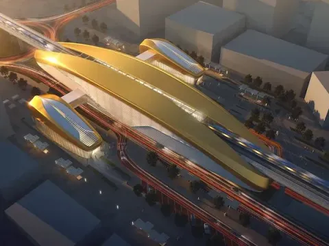
Dubai Metro Blue Line
MEP modelled and coordinated across Blue Line stations and depots for MNG Esmas,…
Read the case
Wynn Ras Al Khaima
Over 100 people at peak across MEP, structural and interior fit-out packages on …
Read the case
Stargate Data Centre
Every N+1 and 2N redundancy path verified in 3D against Tier-rating requirements…
Read the case
Zayed National Museum
Mechanical, electrical and plumbing threaded through Foster + Partners' steel-fe…
Read the case
Emaar Golf Hillside Tower
Shop drawing release synced to the tower pour cycle on AFE's fast-track golf-fac…
Read the caseFrom the journal
Field notes on signage delivery.
 6 min
6 min
From LOD 350 to fabrication-ready
Why "coordinated" models still cause site rework, and the handoff that fixes it.
Read 5 min
5 min
The BEP subcontractors actually follow
The difference between a filed document and a working agreement is five sections.
Read 5 min
5 min
Clash detection to zero
Zero hard-clash is table stakes. Here is the tolerance standard we hold a federated model to before sign-off.
Read 6 min
6 min
QTO as the single source of truth for variations
When quantities come straight from the model, variations stop being arguments and become deltas.
Read 5 min
5 min
As-built from day one
Retrofitting an as-built at practical completion is a tax. Updating it weekly is a habit.
Read